
A boat lift is a fundamental mechanical safeguard for your vessel. Continuous submersion exposes a hull to osmotic blistering, marine biofouling, and galvanic hardware deterioration, while exposing the vessel to the relentless kinetic energy of wake turbulence and tidal shifts.
However, specifying a boat lift system requires a precise calculation of hull dynamics, local hydrographic conditions, and structural dock engineering. Selecting an incompatible lift mechanism or miscalculating mechanical loads can result in structural failure, drivetrain binding, or catastrophic hull deformation.
At MacDuff Marine, we engineer high-performance lift systems tailored to demanding marine environments. This guide analyzes the mechanical classifications of modern boat lifts, structural load criteria, and architectural integration strategies required to select the optimal system for your waterfront infrastructure.
1. Mechanical Classifications of Boat Lift Systems
Boat lifts are engineered around specific structural configurations to solve distinct water-depth, tidal, and space constraints.
Top-Mount vs. Bottom-Mount Piling Lifts
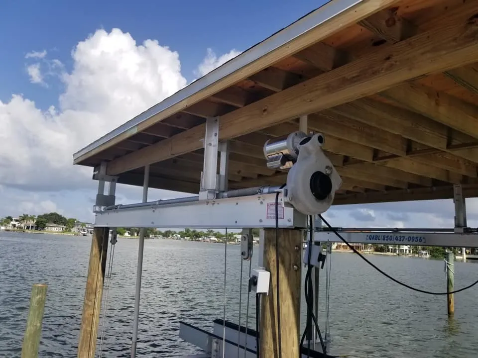
Top-Mount Systems: These systems mount structural drive beams and motorized gear plates directly across the tops of dedicated guide pilings. They are highly recommended for saltwater environments and high-wake coastal canals, as the critical mechanical drivetrains, cables, and motors remain completely elevated above the corrosive splash zone.
Bottom-Mount (Submerged) Systems: These systems utilize a structural cradle assembly that rests on or is pinned directly to the seabed. They are typically reserved for shallow-water applications, inland lakes, or architectural zones where local regulations prohibit high-profile overhead structures.
Cradle Systems vs. Sling Systems
Cradle Lift Configurations: These configurations utilize a rigid, heavy-duty aluminum or steel structural frame outfitted with custom-profiled bunk boards (typically structural aluminum with high-density poly capping). The bunks align directly with the structural stringers of the vessel’s hull. This setup is the industry standard for stepped hulls, deep-V center consoles, and heavy multi-engine configurations because it provides rigid, non-shifting structural support.
Sling Lift Configurations: These configurations utilize high-tensile, marine-grade polymer straps suspended from overhead drive shafts to cradle the hull. Slings reduce localized point pressure by distributing weight across a wide surface area, making them ideal for classic wooden boats, fragile hull designs, or shallow slips where a rigid metal cradle would strike the seabed bottom.
Fixed vs. Floating Lift Architecture
Fixed Piling Lifts: These systems are permanently through-bolted into timber or concrete pilings driven into the seabed. They offer maximum structural rigidity and high weight capacities, making them ideal for stable environments or areas with predictable, moderate tidal ranges.
Floating Pneumatic Lifts: These systems utilize heavy-duty, marine-grade polyethylene displacement tanks filled and purged via a low-pressure air blower system. Floating lifts are highly adaptable, making them the premier choice for deep-water configurations, deep-water marinas, or floating dock networks where the lift must rise and fall in perfect synchronization with extreme tidal fluctuations.
2. Structural Load Calculations and Safety Margins
Miscalculating the total gross weight of a vessel is the leading cause of premature winch, cable, and structural beam failure. Lift capacities are rated based on total operational weight, not the manufacturer’s dry weight specification.
To establish a reliable engineering baseline, MacDuff Marine enforces a strict 25% structural safety margin across all lift specifications to account for dynamic loads and environmental variables.
Total Specified Lift Capacity = (Dry Hull Weight + Fuel/Fluids + Gear/Accessories) x 1.25
When calculating your vessel’s total load profile, you must factor in the following fluid and structural variables:
Fuel and Water Payload: Marine fuel weighs approximately 6.3 pounds per gallon, while fresh water weighs 8.3 pounds per gallon. A center console with a 200-gallon fuel tank and a 30-gallon livewell adds roughly 1,510 pounds of deadweight over the dry hull specification.
Add-On Marine Electronics and T-Tops: Fiberglass hardtops, structural towers, aftermarket radar arrays, outriggers, and anchor anchoring systems (such as shallow-water anchors) must be weighed and aggregated into the base hull profile.
Environmental Accumulation: Rainwater accumulation from a single severe coastal storm can quickly add hundreds of pounds to an uncovered vessel. A safety margin of 25% ensures your hoist motors, cables, and pulleys operate within their engineered load limits during these surge events.
3. Metallurgical Selection: Material Longevity
The chemical composition of your boat lift determines its structural lifespan. Selecting the wrong alloy for your specific water salinity will trigger rapid galvanic degradation.
Marine-Grade Aluminum (6061-T6)
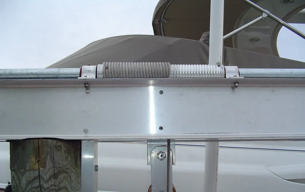
Structural 6061-T6 aluminum is the definitive standard for saltwater and brackish coastal deployments. When exposed to oxygen, aluminum naturally develops a resilient microscopic layer of aluminum oxide that seals the underlying metal against salt corrosion. Aluminum lifts are significantly lighter than steel, reducing deadweight loads on dock pilings while maintaining exceptional tensile strength.
Hot-Dipped Galvanized Steel
Galvanized steel offers high structural yield strength at a lower initial capital cost. However, its corrosion resistance relies entirely on an outer zinc coating. In saltwater environments, this sacrificial zinc layer degrades rapidly. Once the underlying carbon steel is exposed via scratches, friction wear, or hardware friction, the structure will experience severe red rust pitting and structural weakening. Consequently, galvanized steel lifts should be restricted exclusively to freshwater lake applications.
Technical Selection Matrix
To streamline the specification process, use this engineering matrix to align your regional water conditions with the correct lift architecture:
The MacDuff Marine Advantage
A boat lift system is a long-term investment in your vessel’s safety and structural integrity. At MacDuff Marine, we eliminate the guesswork from the configuration process. Our factory-trained technical team conducts comprehensive site assessments, evaluates local hydrographic profiles, and matches your hull design with an engineered, marine-grade lifting solution.
From heavy-duty aluminum top-mount hoists with sealed bearing pulleys to custom-fit bunk profiles, we ensure your lift system functions flawlessly with a mandatory 25% safety overhead for total peace of mind.
Contact the technical support and engineering team at MacDuff Marine today to schedule a site evaluation, calculate your precise vessel load requirements, and select the optimal lift system for your waterfront setup.